NIC Installing NIC drivers in Linux In this guide we install a NIC driver for a Realtek Gigabit Ethernet Card in a Linux Environment as it did not activate by default!
regex Regex / grep: Learning Regex Fast! ++IP Whois CheatSheets! In this guide we go over the power of regex for all your pattern-matching needs!
octoprint OctoPrint Camera Setup In this guide we go over setting up cameras to watch over your 3D print!
octoprint Octoprint Tour Guide In this guide we go through a very basic walk-through for the Octoprint Service which can readily run on a Raspberry Pi.
octoprint Installing OctoPrint into the Raspberry Pi OS / Basic Operation.. In this guide we go over the initial setup and installation of Octoprint on a standard raspberry pi.
raspberry pico Installing and Learning Raspberry Pi (Linux) In this basic introductory guide we go over configuration and setup for a static-IP Raspberry Pi!
DNS Understanding DNS / Naked Domain Routing (Square Space) and how nginx reverse-proxy handles it. In this excellent guide we review the basics of dealing with naked domains and reverse-proxy configurations.
ssh SSH Reverse Tunneling Power Secrets Serving Web Servers From Home. In this wild guide we show how ssh can be used to to punch your home server out to the public internet!
mysql Building a quick mysql / ghost blogdocker container serving a database. In this very good guide we setup a ghost blog locally which connects to a mysql server. We go over how browsers are forcing https connections and we need to turn that off for our local blog!
python3 fdesigner (Python3 rapid tkinter menu creator) This fdesigner presents powerful menu designing capabilities saving you HOURS in your layout designs for tkinter!
kicad Setting up Digikey for Kicad In this quick awesome article we go over installing Digikey's 23,000 schematics to Kicad!
kicad Setting up kicad in ParrotOS In this article we go over a custom installation of kicad onto ParrotOS.
tkinter tkinter Root and Widget Sub-Classing (That works!) In this guide we go over how to properly overload tkinter root and widget classes via 'side-loading' Tkinter has proven to be problematic and class examples are scarce on the internet.
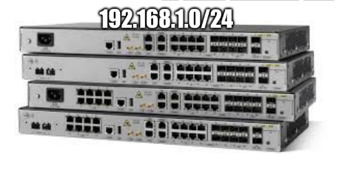
subnet Python Sub-net Calculator Example In this article we produce a simple algorithm for calculating sub-net ranges for any ip / subnet set!
nginx Nginx Docker Logging Setup via Container Volume Sharing In this guide we go over sharing the internal logs of a nginx-reverse proxy with another container that can do the IP decoding and look-ups making nice usage logs.
hacker HoneyPot Fun. Trapping Wordpress Scanners. We start our planning to trap Wordpress scanners (hackers) and feed them bogus and poisonous but giant fake xml files.
docker Saturday Night Dreams. Building a hyper-simple httpd Docker Server in Pycharm Professional In this hyper-quick guide we go over building an entire Python Server / html page inside a docker standalone in 3 short files!
domain Domain Wars. Fighting back against Big Daddy Domain Registration Creepers. In this article we show how to prevent domain fraud, domain hi-jacking, domain renewal gouging, and present a script that will scan for you for unused domains.
flask Python Flask Primer In the Pycharm Professional Environment. We go over Flask, Pycharm Professional, setting up and handling of cookies and sessions in this primer.
certbot Setting up SSL for a Python Server with CertBot. In this article we go over setting up SSL for a Python request server, then adding it to a NGINX reverse-proxy!
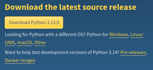
python3.13 Python 3.13 Dockerfile building and testing. In this roll-your-own article we go over setting up our own python container that has rich support for specialized python applications.
qt Qt - Python Quick Reference In this article we build a quick reference for much of the Qt Framework!
mysqli PHP/Mysql Connector TroubleShooting And Setup In this quick review tutorial we go over establishing a back-end access to a mysql server.